6 Loudspeaker cabinets
6.1 Loudspeakers
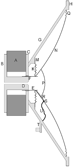
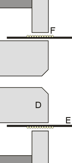
Below is a schematic cross section of a loudspeaker and a close-up of the motor section:
- A permanent ring magnet
- B back pole plate
- C front pole plate
- D vented pole piece
- E voice coil former
- F voice coil inside air gap
- G basket
- H mounting flange
- K spider
- M spider support
- N cone
- P dust cap
- Q surround
- R voice coil wires
- S cone punch tubes
- T connection terminal support
- U cone wires


And here's how it all works: the permanent magnet (A) provides an extremely strong magnetic field (symbol B, a.k.a. as flux, typically 1 Tesla) inside the air gap (F). The magnetic field is directed there by the pole plates (B/C) and the pole piece (D). The better part of the voice coil (F) is inside this circular slot, and is held there by the tubular voice coil former (E), which is held in place by the spider (K). Electric current through the voice coil will induce a magnetic field, and, by Lorentz' law, a force is the result. The coil puts the cone (N) in motion, which will, with its large surface, move air. The spider's second task is to provide most of the cone suspension (specified as Cms  ). It makes the cone move back to its resting position. The cone itself is centered by the surround (Q), which is usually made of rippled impregnated cloth. The surround also provides a part of the suspension and damps the unwanted surface vibrations (called "cone break-up") of the cone.
© Joris van den Heuvel 2001-2009

 PREV
PREV